


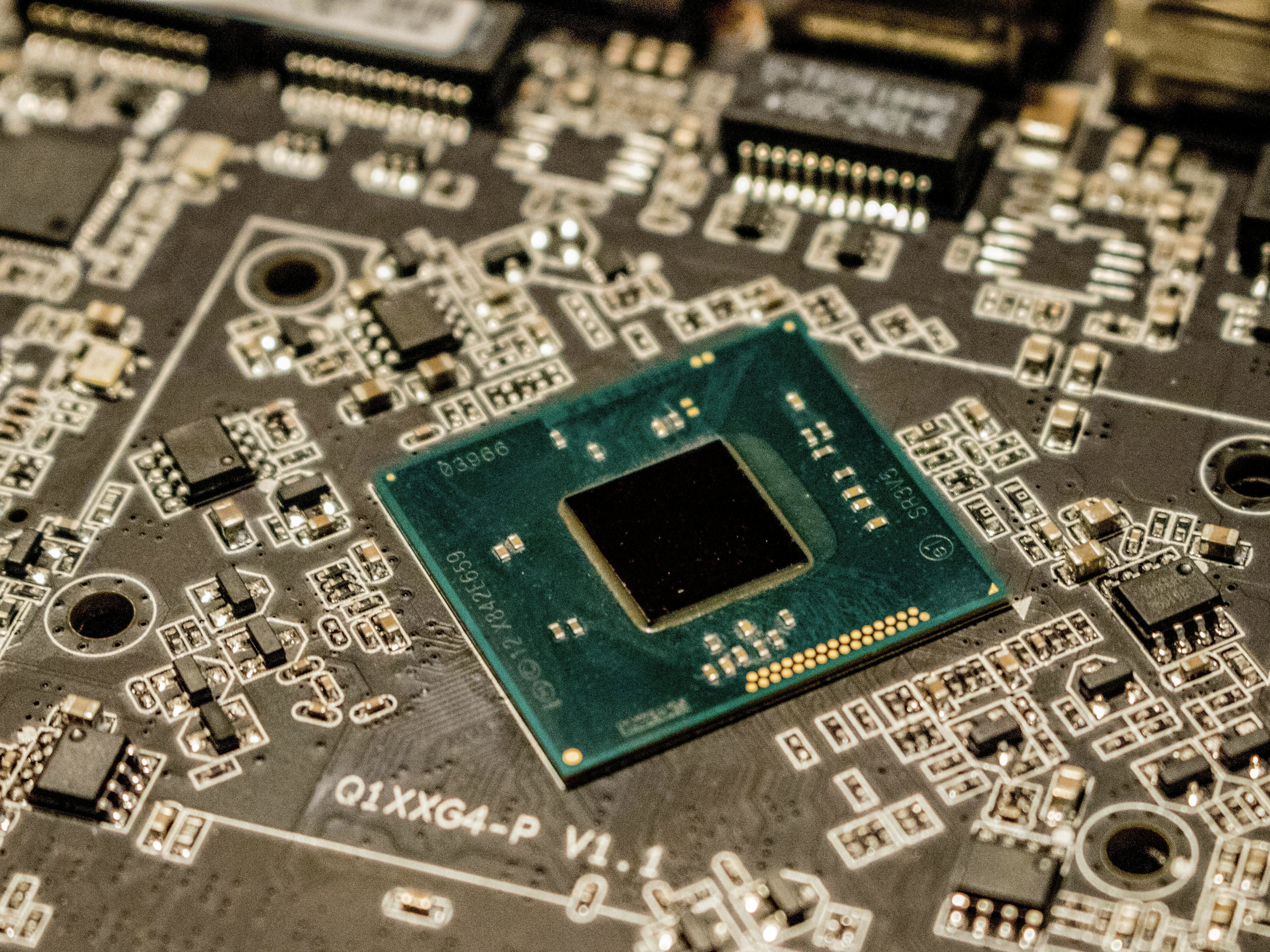


SLW8308B(BGA) Transceiver for 5.5G/6G Satcom Application
SLW8308B is a CMOS silicon on insulator (SOI), 24GHz to 44GHz, mmWave 5.5G/6G Satcom beamformer, with IF up/down conversion and an on-chip frequency synthesizer.
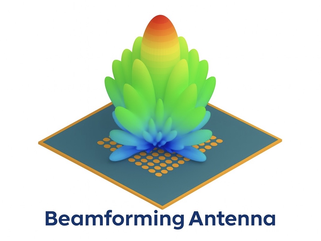
The SLW8308B drives 4 horizontal and 4 vertical polarized antennas via independent RFV and RFH bond pads. A 52MHz external reference signal is required to generate LO signal.
In transmit mode, the signal at the IF input pin is up-converted to RF by mixing with the LO signal. This RF signal drives 8 independent transmit channels via the 1:8 power splitter. The transmit channels feed the 8 RFV/RFH antenna ports. In receive mode, the RF input signals pass through the 8 receive channels and combine via the 8:1 power combiner. The combined RF signal is down-converted to IF by mixing with LO signal to drive the IF pin. In both modes, each transmit and receive channel includes a phase shifter (PS) to control the phase, and variable gain amplifiers (VGAs) to control the amplitude. The phase shifter has a full 3600 phase adjustment range in either transmit or receive mode, with 5 bits of resolution (expandable to 9 bit resolution).
The RFV and RFH bond pads can be connected directly to a 5.5G/6G Satcom mmWave antenna array. The SLW8308B can be programmed using a 3-wire serial port interface (SPI). Various SPI modes are available to enable fast startup and control during normal operation. The amplitude and phase for each channel can be set individually, or multiple channels can be programmed simultaneously using the on-chip SPI for beamforming.
Application
- Telecommunications Industry
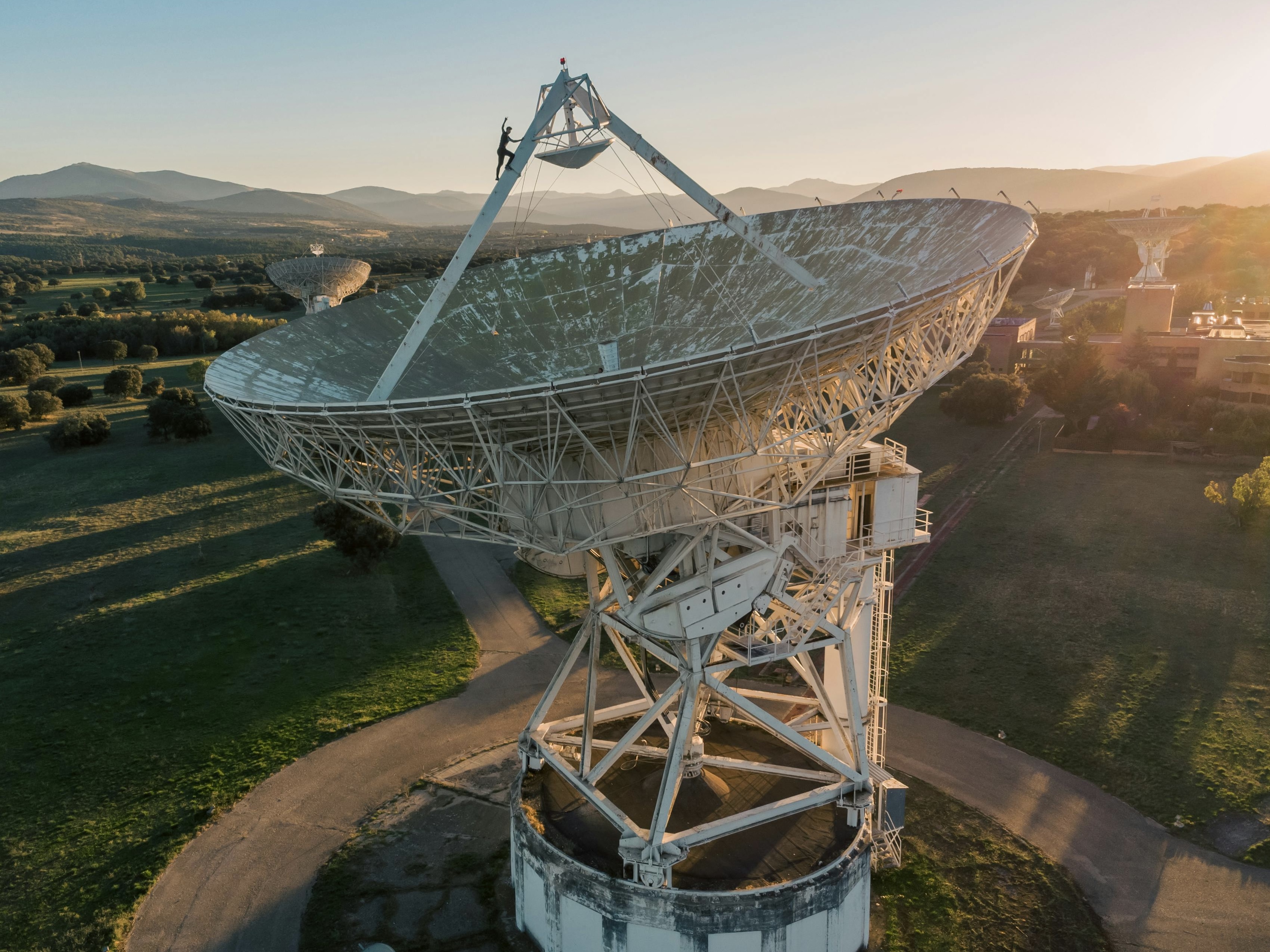
- Next Generation 5.5G/6G Satcom Networks and Infrastructure
- Fixed Wireless Access (FWA)
- Repeaters
- Smartphones (integrated PLL) – SAT2PHONE.
- Internet of Things (IoT)
- High-bandwidth Internet of Things devices and applications
- Artificial Intelligence (AI)
- Data Transfer up to 18 Gbps.
- Automotive Industry
- Connected vehicles, autonomous driving and vehicle-to-everything (V2X) communication
- Smart Cities
- Urban infrastructure, public safety and intelligent transportation systems
- Low-Altitude Economy
- Customer Premises Equipment (CPE)
- Ka-Band Satellite Communication
IF Operation:
- Variable IF between 3.5-10GHz
- Integrated PLL.
- External clock 52 MHz

Key Features
• RF range: 24.0 GHz to 44.0 GHz,
• Supported bands: n257, n258, n259, n260, n261,
• 8 channels, dual polarized,
• 5-bit PS resolution for phase control.
• Amplitude control by VGA,
• Beam positions calibration by PS and VGA,
• Fast TDD switching of the transmit and receive channels,
• Supports 3/4-wire SPI up to 1 MHz SPI clock speed,
• High-speed digital SPI-based interface,
• Fast beam switching drive 4 horizontal and 4 vertical antenna ports,
• Matched with 50 Ω single-ended RF input and output,
• Three power supply: 1.8V, 1.0V, and 3.0V,
• Package: 6.25mm x 6.25mm x 0.9mm, 72 balls Ø0.4mm, 0.65mm patch.
Transmit operation per channel:
• OP1dB: +16dBm Typ,
• High linear nominal gain: 8dB Typ.
Receive operation per channel:
• High gain: 25 dB Typ,
• Low Noise Figure 4.2 dB Typ.
• High Linearity: IIP3 = -8 dBm Typ
SLW8308 Transceiver for 5.5G/6G Satcom Application
SLW8308 is a CMOS silicon on insulator (SOI), 24GHz to 44GHz, mmWave 5.5G/6G Satcom beamformer, with IF up/down conversion and an on-chip frequency synthesizer.
The SLW8308 drives 4 horizontal and 4 vertical polarized antennas via independent RFV and RFH bond pads. A 52MHz external reference clock is required to generate LO signal.
In transmit mode, the signal at the IF input pin is up-converted to RF by mixing with the LO signal. This RF signal drives 8 independent transmit channels via the 1:8 power splitter. The transmit channels feed the 8 RFV/RFH antenna ports. In receive mode, the RF input signals pass through the 8 receive channels and combine via the 8:1 power combiner. The combined RF signal is downconverted to IF by mixing with LO signal to drive the IF pin. In both modes, each transmit and receive channel includes a phase shifter (PS) to control the phase, and variable gain amplifiers (VGAs) to control the amplitude. The phase shifter has a full 3600 phase adjustment range in either transmit or receive mode, with 5 bits of resolution (expandable to 9-bit resolution).
The RFV and RFH bond pads can be connected directly to a 5.5G/6G Satcom mmWave antenna array. The SLW8308 can be programmed using a 3-wire serial port interface (SPI). Various SPI modes are available to enable fast startup and control during normal operation. The amplitude and phase for each channel can be set individually or multi- channels can be programmed simultaneously using the on-chip SPI for beamforming.
Application
- Telecommunications Industry
- Next Generation 5.5G/6G Satcom Networks and Infrastructure
- Fixed Wireless Access (FWA)
- Repeaters
- Smartphones (integrated PLL) – SAT2PHONE.
- Internet of Things (IoT)
- High-bandwidth Internet of Things devices and applications
- Artificial Intelligence (AI)
- Data Transfer up to 18 Gbps.
- Automotive Industry
- Connected vehicles, autonomous driving and vehicle-to-everything (V2X) communication
- Smart Cities
- Urban infrastructure, public safety and intelligent transportation systems
- Low-Altitude Economy
- Customer Premises Equipment (CPE)
- Ka-Band Satellite Communication
IF Operation:
- Variable IF between 3.5-10GHz
- Integrated PLL.
- External clock 52 MHz

Key Features
• RF range: 24.0 GHz to 44.0 GHz,
• Supported bands: n257, n258, n259, n260, n261,
• 8 channels, dual polarized,
• 5-bit PS resolution for phase control.
• Amplitude control by VGA,
• Beam positions calibration by PS and VGA,
• Fast TDD switching of the transmit and receive channels,
• Supports 3/4-wire SPI up to 1 MHz SPI clock speed,
• High-speed digital SPI-based interface,
• Fast beam switching drive 4 horizontal and 4 vertical antenna ports,
• Matched with 50 Ω single-ended RF input and output,
• Three power supply: 1.8V, 1.0V, and 3.0V,
• Package: 5.56mmx5.63mmx230um, 214 C4 ball bumps with Ø80um.
Transmit operation per channel:
• OP1dB: +16dBm Typ,
• High linear nominal gain: 8dB Typ.
Receive operation per channel:
• High gain: 425 dB Typ,
• Low Noise Figure 4.2 dB Typ.
• High Linearity: IIP3 = -8 dBm Typ